PMP Network Devices
The Network Device connects to one or more Subscriber Sites to create links to Subscriber Modules.
Creating Network Devices
To create a new Network Device from the map view, click ![]() on the right panel of the project window. This opens the Network Device Mode window.
on the right panel of the project window. This opens the Network Device Mode window.
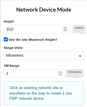
New Network Device Mode
To use the height of an existing network site, tick Use the site Maximum Height? For new sites or to override the network site height leave this box unticked and set the required height. Set the Range Units and SM Range to configure the furthest point at which SMs can connect to the Network Device.
To add a network device to an existing site, click on the site. Multiple network devices can be added to the same site, they will be separated by the beamwidth of the antenna or the Modeled Beamwidth if it has been set to a different value.
To create multiple Network Devices Click ![]() OR
OR ![]() in the left panel of the page.
in the left panel of the page.
This displays the PMP Tables page. Click on the Network Devices tab.
Click ![]() to create new PMP Network Devices
to create new PMP Network Devices
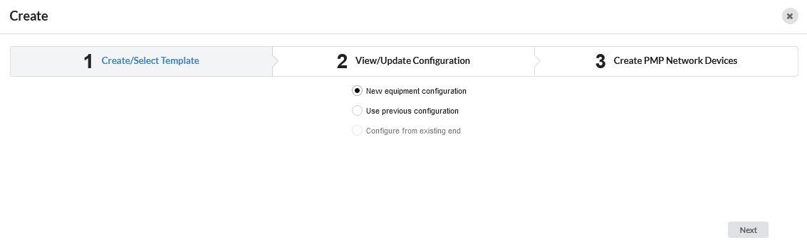
This displays the Create/Select Template page.
Select New equipment configuration and click ![]() to create a first template or select Use previous configuration to choose from an existing template. If there are existing Network Devices, then the Configure from existing end option will also be available.
to create a first template or select Use previous configuration to choose from an existing template. If there are existing Network Devices, then the Configure from existing end option will also be available.
Create/Select Template
Enter the parameters required to configure the network device, see Network Device Equipment and subsequent sections for details on each of the parameters and click ![]()
The Create PMP Network Device page is displayed
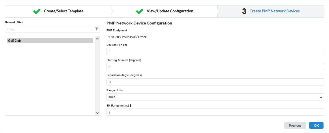
PMP Network Device Configuration
Select the sites from the left hand list. The search field narrows the choice when there is a large number of sites in the list.
From the right hand side menu, configure the following:
Enter the number of Network Devices required on each site
Enter the azimuth of the first Network Device on the site.
The separation angle defaults to 360 degrees divided by the number of Network Devices, select a different angle if required.
Set the Range Units and the SM Range of the sectors and click
 .
.
Displaying PMP Network Devices
When PMP Network Devices have been created they appear in the PMP Tree view and Table views. To see the tree view, click the ![]() which is beside the PMP tool bar. To change to the table view, click on
which is beside the PMP tool bar. To change to the table view, click on ![]() OR
OR ![]() . To manage the table view see User Interface Tips.
. To manage the table view see User Interface Tips.

To locate Network Devices in the map view from the details page, click the
 icon, which is displayed next to the
  icon at the top.
Deleting a Network Device
To delete a Network Device, hover over the Network Device in the PMP tree view and click  , click
 ![]() on the details page, select rows and click
on the details page, select rows and click  in the table view, or right-click on the Network Device in the map view and select Delete from the pop-up menu.
Deleting a Network Device will delete all links to Subscriber Modules connected to the Network Device. The Subscriber Sites will not be deleted and will be available to connect to other Network Devices.
To revert the changes made, click the
 icon, which is displayed next to the Apply button. This icon is only displayed when there are changes to the parameters, replacing the icon.
PMP Network Device Page
The Network Device page includes the following features:
Each section begins with a gray title bar. Click on this bar to open or close the section.
The numeric data entry fields can be incremented or decremented in steps by using the up and down arrow keys. Use this feature to evaluate the impact of step changes on link performance.
If a field is highlighted in pink, its value is out of the permitted range.
General
Enter the Name and Description of the Network Devices. The MAC Address and MSN of the equipment may also be added.
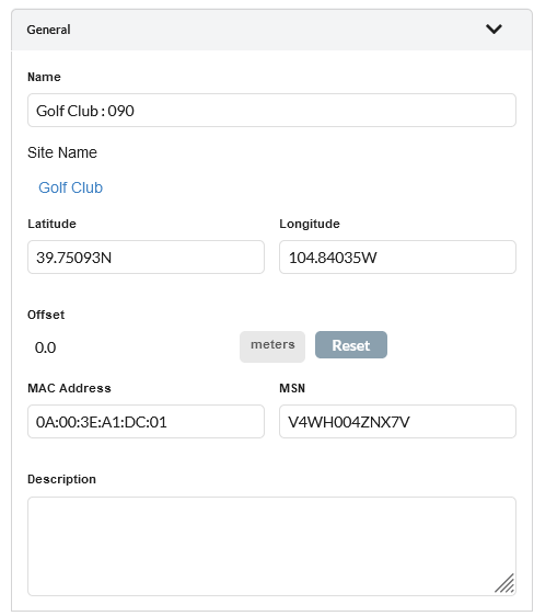
Network Device General
To move a Network Device to a different location from the Network site coordinates enter new coordinates in the Latitude and Longitude fields. The Offset value will show the distance between the Network Device and the central Network Site location, the ND can only be moved up to 100 m (328 ft) from the central Network Site location. If the distance is greater than this, the offset value is shown in red and it is not possible to Save. When the offset is less than 100m click Save to move the Network Device to the new location, which will automatically update the profiles for all subscribers connected to it. Select Reset to move the ND back to the central network site coordinates.
Equipment
Select the frequency band, equipment and country for the Network Device. The fields that are displayed in the “Equipment” box will change depending on the type of equipment selected.
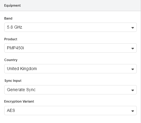
Network Device Equipment
Equipment Parameters
Band: Select the frequency band used by the Network Device. Changes to Band Carrier 1 when there is more than one carrier (PMP 450v only)
Product: Select the PMP product.
Color (PTP 700 HCMP only): Select the color of the radios, the same color will be used at the Network Devices and for all connected subscribers.
Capacity (PTP 700 HCMP only): Select the capacity varient of the radios.
Country: Select the country in which the Network Device is located.
Sync Input (PMP 450 and 450i only): Select the synchronization option for the link (information only).
Encryption Variant (PMP 450 and 450i only): Select the encryption option for the link, used for product selection only.
Number of Carriers (PMP 450v only): Select the number of carriers for the Network Device.
Band - Carrier 2 (PMP 450v only): Select the second carrier band for the Network Device. This field is available only when the number of carriers is more than 1.
MIMO Mode (PMP 450m and ePMP 3000 only): Select the MIMO operating mode. For PMP 450m choose Sector mode to report ND performance in Legacy mode using the standard PMP 450 capacity scheduler or choose Mu-MIMO to report cnMedusa ND Performance.
I/O Connectivity (N500 Only): Select Expanded to get the additional IO port, used for product selection only.
Sync Input (N500 Only): Select the synchronization option for the link.
Product Configuration
Select the product parameters. The fields that are displayed in the “Product Configuration” box will change depending on the type of equipment selected. For example, when a PMP 450i is selected, the Color Code field is displayed.
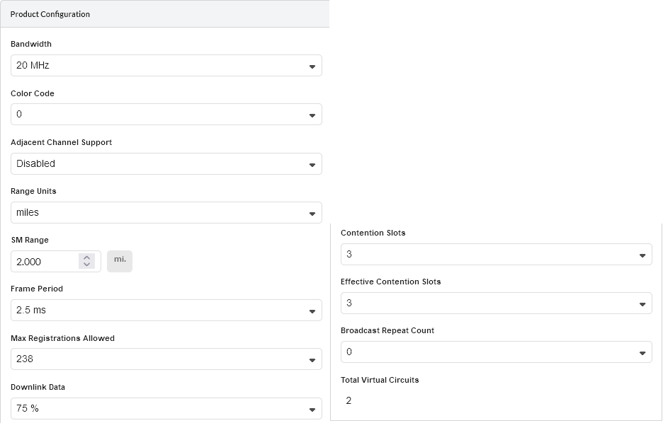
Network Device Product Configuration
Some parameters are required when configuring the product but are currently not used in the LINKPlanner calculations, they will be used in future releases. These items are identified as “(information only)” in the descriptions below.
Product Configuration Parameters
Band Setting (N500 Only): Select ISM or Licensed.
T/R Spacing (N500 Licensed Only): Select the difference between transmit and receive frequencies (MHz).
Bandwidth: Select the channel bandwidth. Available under Component Carriers section for PMP 450v 4x4 ND.
Asymmetric Uplink Bandwidth (ePMP 11ax only): Select the channel bandwidth for uplink.
Channel (60 GHz cnWave Only): Select the Frequency and Channel number.
Modulation Type (N500 ISM Only): Select the group of modulation modes to use.
Color Code / Golay Code: Select the Color Code for the Network Device (information only), called Golay Code on 60 GHz cnWave.
Adjacent Channel Support (PMP 450 family Only): Select Enabled if using adjacent channels on adjacent sectors. This option only applies to the 3 GHz bands (all SMs) and to the 5GHz band for PMP 450b SMs.
Polarity (60 GHz cnWave Only): Set to Odd or Even. If the two sectors on the DN are set to opposite polarities this represents a Hybrid mode and the throughput is halved.
Range Units: Select the units for the SM Range.
SM Range: Set the maximum range for the Network Devices sector size. Subscriber sites beyond this range will not be shown as valid subscriber module options and if the SM Range is reduced after adding Subscribers, any subscribers beyond this range will be shown as invalid (i.e. in red).
SM Modulation Mode (N500 Only): Select the modulation mode to be used by the SM equipment.
SM Maximum Mod Mode (N500 Only): Select the maximum modulation mode that the SM equipment will use in adaptive mode. Only displayed when Adaptive modulation is selected.
SM Minimum Mod Mode (N500 Only): Select the minimum modulation mode that the SM equipment will use in adaptive mode. Only displayed when Adaptive modulation is selected.
DN Modulation Mode (N500 Only): Select the modulation mode to be used by the DN equipment.
Hop Pattern (N500 only): Select the uniform step interval for DTS modulations. A value of 0 sets the frequency to a single channel, a value of 1 creates a pseudo random hopping sequence. A value of 1 must be used when Modulation Type = FHSS.
MMS Hop Offset (N500 only): Select the MMS Hop Offset for the link.
DN Max Payload Bytes (N500 only): Set the maximum packet size at the DN. Maximum value is 1600 Bytes. Minimum value for fixed modulation mode is 64 Bytes, in adaptive mode, the minimum may be higher than this dependent on the configured Max and Min Modulation modes. Reducing the packet size will reduce the data rate from the quoted data rate per mode.
SM Max Payload Bytes (N500 only): Set the maximum packet size at the SM. Maximum value is 1600 Bytes. Minimum value for fixed modulation mode is 64 Bytes, in adaptive mode, the minimum may be higher than this dependent on the configured Max and Min Modulation modes. Reducing the packet size will reduce the data rate from the quoted data rate per mode.
Hi (N500 only): Set the end which will take the higher frequency when using FDD frequency assignments
Frame Period: Select the Frame Period.
Downlink Data (PMP 450 and 450i Only): Set the proportion of the link to be used for downlink data.
Maximum Mod Mode (ePMP and 60 GHz cnWave Only): Set the maximum modulation for the Network Device on the downlink to all Subscribers.
DL/UL Ratio (ePMP Only): Select the required DL/UL Ratio.
Contention Slots (PMP 450 and 450i Only): Set the number of contention slots required.
Broadcast Repeat Count (PMP 450 and 450i Only): Select the value required (information only).
Total Virtual Circuits (PMP 450 and 450i Only): Calculated value based on the number of Subscriber Modules, 1 per Subscriber Module plus 1 additional circuit for each Subscriber Module which has High Priority Channel set to Enabled.
CN Capacity Limit (60 GHz cnWave Only): percentage of maximum traffic which is allowed for use by Client Nodes, with the remainder reserved for use by the mesh links to other DNs.
Max Registrations Allowed (cnWave 5G Fixed, ePMP, PMP 450 and 450i Only): Set the maximum number of Subscribers allowed on the Network Device.
Max CN Registrations Allowed (60 GHz cnWave Only): Set the maximum number of Client Nodes allowed on the DN, noting that each DN can also support mesh links to two other DNs.
Max Slaves Allowed (PTP 670 and 700 HCMP Only): Set the maximum number of Slaves allowed on the Network Device.
Synchronization Source (ePMP Only): Set the required Synchronization Source, select None to use the Integrated or Unsynchronized Connectorized Network Device.
Sync (PTP 670 and 700 HCMP Only): Select the synchronization setting for the link.
TDD Frame Mode (PTP 670 and 700 HCMP Only): Only Standard Mode.
Symmetry (PTP 670 and 700 HCMP Only): Select the link operation (Adaptive, Symmetric, 2:1, 3:1 or 4:1 - options are dependent on bandwidth and other configuration settings).
Dual Payload (PTP 670 and 700 HCMP Only): Allow dual-payload modulation modes for better throughput.
Highest Mod Mode (PTP 670 and 700 HCMP Only): Select the highest modulation mode for the Ethernet traffic to limit the maximum throughput rate, default is 256 QAM 0.81 (no limit). Dual or Single will be automatically selected depending on the setting for Dual Payload.
Lowest Ethernet Mode (PTP 670 and 700 HCMP only): Select the lowest modulation mode for the Ethernet traffic to achieve the required throughput rate, default is BPSK 0.63 Single.
Antenna Configuration
Select the antenna and its height and orientation.
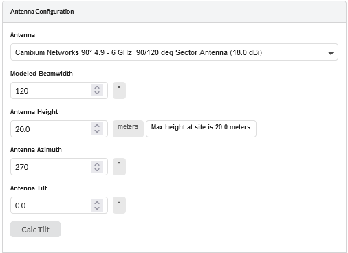
Network Device Antenna Configuration
Antenna Configuration Parameters
Antenna Selection: Select the antenna for the Network Device.
Modeled Beamwidth: Set the beamwidth angle that will be used for planning purposes. This will control the appearance of the network device on the map views and it will be used to determine if subscriber sites are in range.
Antenna Height: Select the height of the Network Device above ground level.
Antenna Azimuth: Set the bearing of peak of beam of Network Device antenna.
Antenna Tilt: Set the angle of mechanical tilt of the Network Device antenna, enter downtilt as a negative value (not available for omni antennas).
Calc Tilt: Select to calculate the optimum mechanical tilt angle for maximum throughput.
Calculate Loss: (N500 Only). Tick the Calculate box to select the type of cable that connects the radio to the antenna. The Cable Loss field is automatically updated.
Cable Length: (N500 Only). The length of cable required to connect the radio to the antenna. The Cable Loss field is automatically updated.
Cable Loss: Loss of the cable between the Network Device and the antenna, read only value for most antenna options.
Power Panel
Set the power and interference parameters.
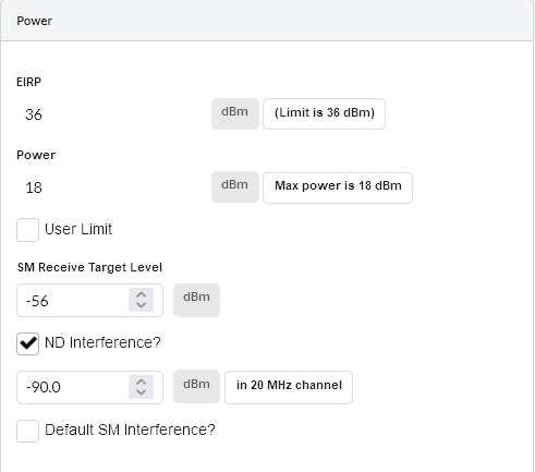
Network Device Power
Power Parameters
EIRP: Read only value for all products except PMP 450m, showing the EIRP of the antenna, if the country selected has a regulatory limit this value is shown in brackets underneath.
Power: Read Only. If the country selected has a regulatory limit (or an implied limit to meet the EIRP limit) the value is shown as “Max Power” in brackets underneath. To set the transmit power for the Network Device to a lower value tick the User Limit box and enter the value in the box below it.
SM Receive Target Level: (ePMP and 450 family only) Set the receive power required at the Network Device from each of the Subscribers.
ATPC HCMP Master Target Rx Power (PTP 670 and 700 HCMP Only): Set the receive power required at the Network Device from each of the Slaves.
ND Interference: This is the amount of site noise in the selected channel bandwidth, expected at the antenna connector of the ND. This noise is assumed to be a constant power added to the thermal noise of the front end of the radio. The bandwidth displayed depends on the bandwidth selected in the Equipment Settings box (in this example it is 20 MHz). To enter Interference, tick the box and update the default value. If the Network Device has been set up and background power measurements are available, then use these measurements. Available under Component Carriers section for PMP 450v 4x4 ND.
Default SM Interference: Select this option to set the same interference level to every SM attached to the ND. This is the amount of site noise in the selected channel bandwidth, expected at the antenna connector of the SM. This noise is assumed to be a constant power added to the thermal noise of the front end of the radio. The bandwidth displayed depends on the bandwidth selected in the Equipment Settings box (in this example it is 20 MHz). To enter Interference, tick the box and update the default value. Use the Interference on the Subscriber Module Equipment to adjust the level for an individual SM. Available under Component Carriers section for PMP 450v 4x4 ND.
To update subscriber module parameters and performance calculations after editing Network Device parameters, click
.
Calculating Tilt Angle
To calculate the optimum tilt angle for a Network Device (the mechanical tilt required to give maximum throughput) select the Calc Tilt ![]() option to display the Calculate Tilt Dialog.
option to display the Calculate Tilt Dialog.
Attach all the required subscriber modules to the Network Device before running this command.
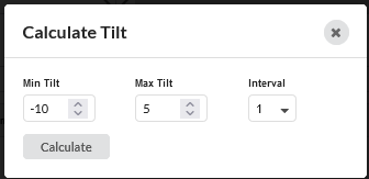
Calculate Tilt Dialog
The dialog shows a number of options:
Min Tilt: Set the minimum tilt angle to consider when running the calculations. The default is the minimum downtilt of the antenna.
Max Tilt: Set the maximum tilt angle to consider when running the calculations. The default is the maximum uptilt of the antenna.
Interval: Set the step interval to define the intermediate tilt angles in the results list. Use a large value if the difference between the Minimum and Maximum is large, reduce the interval for smaller ranges.
Calculate: Start the calculation.
Cancel: Cancel the calculation from running.
Apply Tilt: Apply the selected tilt angle to the network device. The network device will not update unless this command is executed.
When the calculation has finished running, the results are shown below the configuration settings. The angle that offers the maximum throughput has its radio button activated and is automatically selected. If multiple angles offer the same throughput then the middle angle is selected. To use a different angle, select the radio button next to the required row. Select Apply Tilt to update the Network Device to the new tilt angle. The  exports the results to a CSV file.
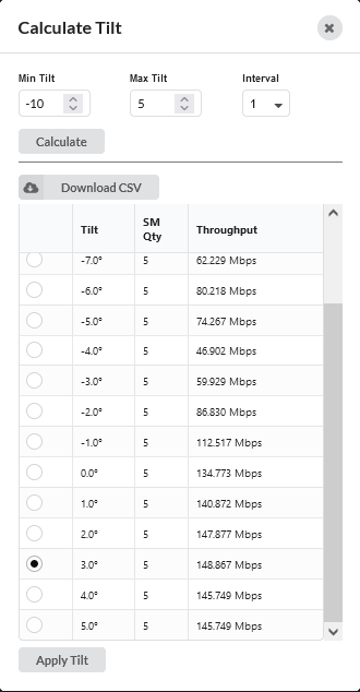
Completed Tilt Calculation Run
Component Carriers
Component Carriers section is only available for the PMP 450v 4x4 Network Device. In this section, select the channel bandwidth, frequency, and enter interferences for the carriers.
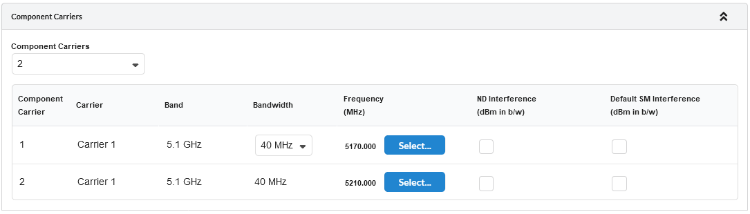
Component Carriers
Component Carrier Configuration Parameters
Component Carriers: Select the number of Component Carriers for the network device.
Component Carrier: Read only value. This is the Component Carrier number assignment.
Carrier: Read only value. Name of the Carrier.
Band: Read Only value. This is the Carrier band selected.
Bandwidth: Select the channel bandwidth for the Component Carriers.
Bandwidths have to be the same for the Component Carriers.
Frequency (MHz): To select the Component Carrier frequencies, click on
. The Select Transmit Frequencies dialog is displayed.
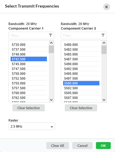
Select Transmit Frequencies
Select the frequency for the component carrier and, if there are multiple component carriers, the available frequencies for the other component carriers are filtered to show only valid Tx frequencies. Select the frequencies from the modified list.
Click Clear Selection to remove selected frequencies from the list.
Select the channel raster from the Raster parameter dropdown list.
ND Interference: This is the amount of site noise in the selected channel bandwidth, expected at the antenna connector of the Carrier. This noise is assumed to be a constant power added to the thermal noise of the front end of the radio. To enter Interference, tick the box and update the default value. If the Carrier has been set up and background power measurements are available, then use these measurements.
Default SM Interference: Select this option to set the same interference level to every SM attached to the Carrier. This is the amount of site noise in the selected channel bandwidth, expected at the antenna connector of the SM. This noise is assumed to be a constant power added to the thermal noise of the front end of the radio. To enter Interference, tick the box and update the default value. Use the Interference on the Subscriber Module Equipment to adjust the level for an individual SM.
Mesh Links
Mesh Links are only available for 60 GHz cnWave products. View, add, delete and modify Mesh Links on the Distribution Node (DN). To manage the table view see User Interface Tips.
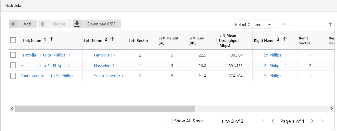
Mesh Links View on Network Devices page
Links to Subscriber Modules
View, add and delete Subscriber Modules on the Network Device.

Links to Subscriber Module View on Network Device page
To add additional Subscriber Modules at the Network Device, click  . A list of available subscriber sites will be displayed. Any subscriber sites which are not connected to the Network Device will be highlighted. To create an additional Subscriber Module at the same subscriber site select the required subscriber site and a duplicate Subscriber Module is created.
To delete a Subscriber Module at the Network Device, select the Subscriber row and click .
To export the data in the Subscriber Module table to a csv file, click
To manage the table view see User Interface Tips.
Performance Summary
This section provides a summary of the Maximum Usable Modulation Modes of all the PMP Links on the Network Device and the Mean Predicted Throughput per modulation mode and for the ND. These values assume that all subscribers are evenly loaded and using the modulation modes shown, it does not include the capacity limits of individual subscribers.
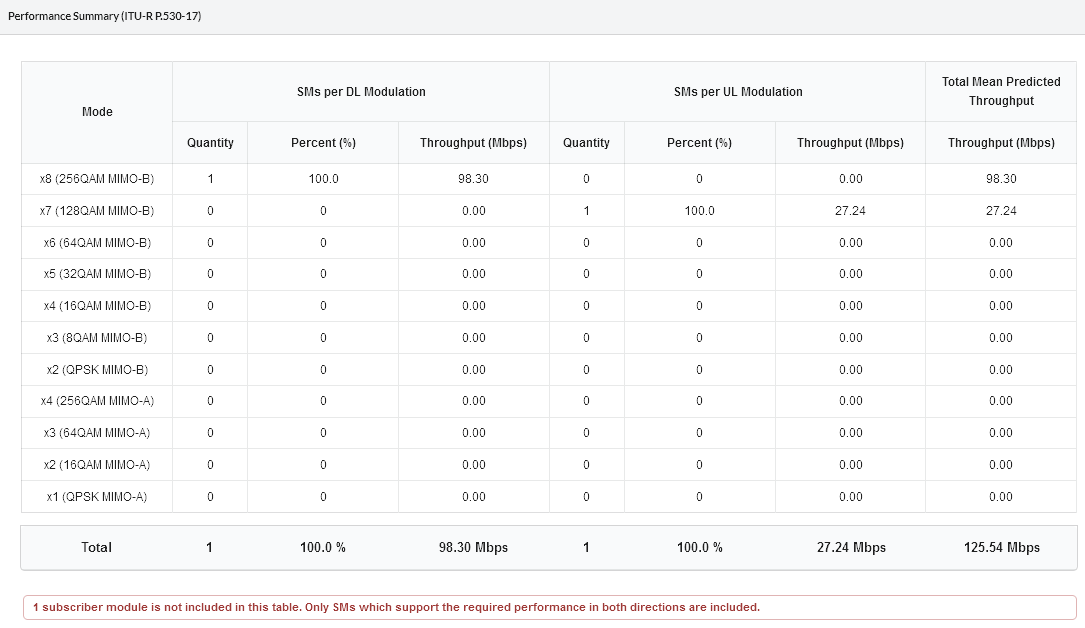
Performance Summary for the Network Device
For 60 GHz cnWave and PMP 450v 4x4 (when Number of Carriers is more than 1), the Performance Summary is shown separately for the Aggregate, Sector 1 (Component Carrier 1) and Sector 2 (Component Carrier 2) in tabs.
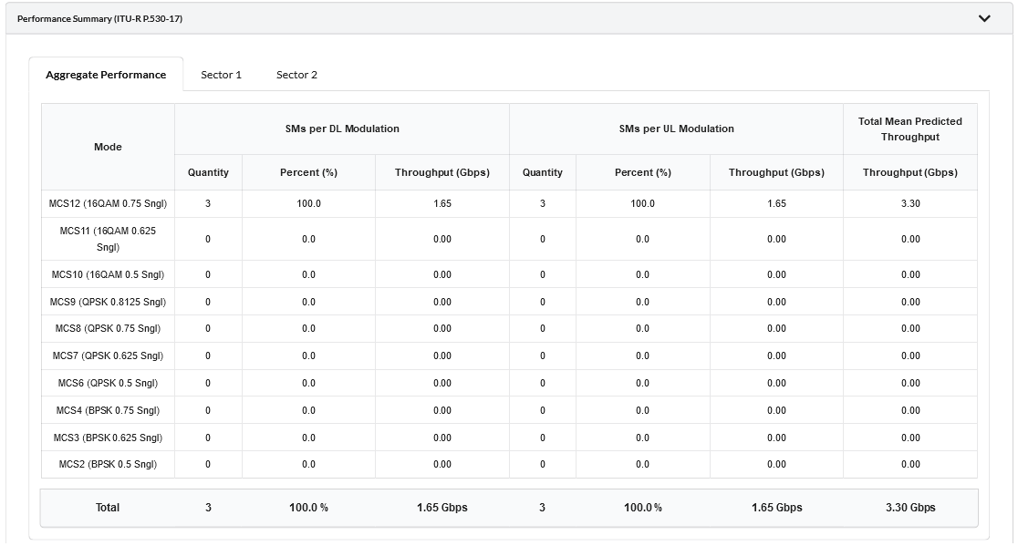
Performance Summary for the Network Device with Multiple Sectors (Component Carriers)
A PMP Link will only be included in the summary if it supports a modulation mode at the required performance level in both directions of the link. A warning will show the number of PMP Links which don’t meet this criteria.
Bill of Materials
To display the Bill of Materials for the Network Device and associated Subscriber Modules select the clipboard symbol ![]() next to the Save button.
next to the Save button.
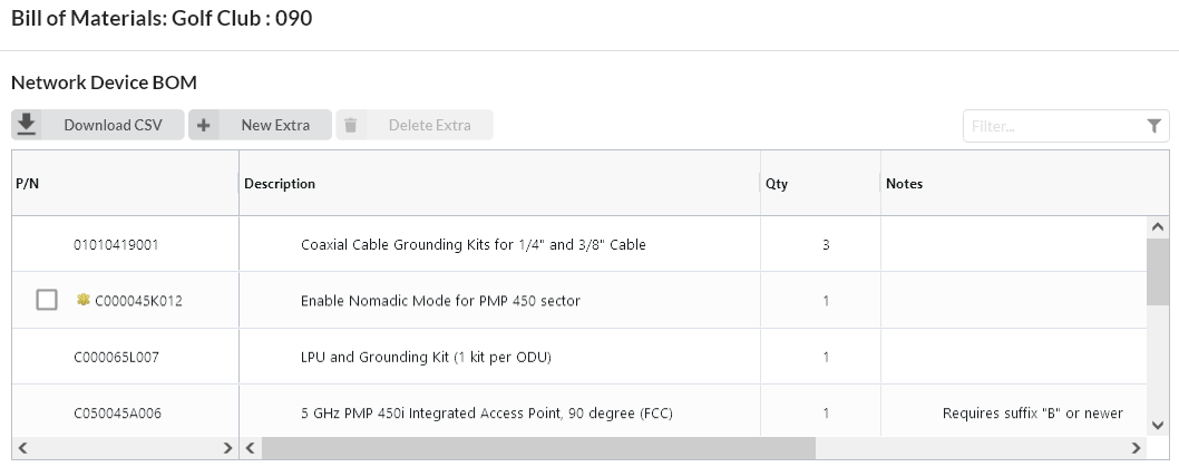
Bill of Materials for PMP Network Device
LINKPlanner automatically calculates the Bill of Materials (BOM) for the required components of the Network Device. The Network Device BOM contains the list of part numbers and associated quantities. To add additional items to the BOM, click ![]() . A list of optional extras for the Network Device will be displayed. To add items to the BOM tick the box next to each item required and click OK. The item will appear in the main list, where the quantity can be adjusted by selecting the number in the Qty column and adjusting as required. To delete optional items from the BOM list, tick the box next to each item and click
. A list of optional extras for the Network Device will be displayed. To add items to the BOM tick the box next to each item required and click OK. The item will appear in the main list, where the quantity can be adjusted by selecting the number in the Qty column and adjusting as required. To delete optional items from the BOM list, tick the box next to each item and click ![]() . A star denotes optional extras which have been added to the automatic BOM items. To power the Network Device from the switch tick the Power from switch? box.
. A star denotes optional extras which have been added to the automatic BOM items. To power the Network Device from the switch tick the Power from switch? box.
When Power from switch is selected, where possible the PoE and line cord are removed from the BOM, which may result in the kit part number changing to a different kit that doesn’t include a PoE. This is not available for all products and country variants.
The Power from Switch option is only available if the network site has a switch attached to it, see Adding Switches and the product selected can be powered by the switch, which includes most of the PoE powered Cambium radios.
If TX2000 is the Sync option on PTP 670 HCMP/PTP 700 HCMP the Network Device will automatically be configured to be powered from the switch.
Bill of Materials for Network Device
P/N: The Cambium part number. If the component is not supplied by Cambium, this is set to ‘(no part number)’.
Description: Description of the components.
Qty: Quantity required. This value can be edited, for items automatically added if the quantity is increased the row will be shown in green, if the quantity is decreased from the recommended value, the row will be shown in red. To reset to the default value, click on the value and choose ![]() .
.
Notes: Displays information about certain items, such as whether they are obsolete.
Bill of Materials for Subscriber Modules
The Subscriber Modules BOM displayed in the Network Device page contains an aggregate view of all the equipment required for the Subscribers connected to the Network Device. This BOM cannot be edited at this level. To change the quantites or add Optional Extras, select the individual Subscriber Modules.

Aggregate Bill of Materials for Subscriber Modules on a Network Device
Viewing & saving the BOM file in MS Excel
To view the Network Device BOM or Subscriber Module Aggregate BOM in Excel, click in the appropriate BOM section. Once in the spreadsheet the file can be saved as normal.
All numeric only part numbers consist of 11 digits, if the number displayed is only 10 digits the part number should start with a zero.