Link Description and Equipment
Link Description
Enter the Name and Description of this link.
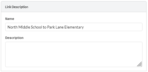
Link Description
Equipment (unlicensed bands)
Select the equipment, regulation and optimization method for this link. The fields that are displayed in the “Equipment” box will change depending on the type of equipment selected. For example, when a PTP 450 family product is selected, the Encryption Variant field is displayed.
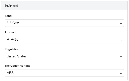
Equipment (unlicensed bands)
Equipment Parameters
Band: Select the frequency band used by the link.
Product: Select the PTP bridge product.
Remote Product: (PTP 700, ePMP and 450 family only) Select a different PTP bridge product for the remote end of the link. The link will default to the same product at both ends of the link.
Color: (PTP 700 only) Select the color of the radios.
Capacity: (PTP 700 only) Select the capacity variant required.
Regulation: Select the regulation that applies to the region in which the link is located.
Encryption Variant: (PTP 450 family only.) Select the encryption option for the link, used for product selection only.
Number of Carriers/Component Carriers: (PTP 450v family only) Select the number of Carriers and Component Carriers for the product.
Precise Network Timing: (PTP 670 and 700 only) Select Enable to add license key for IEEE1588 and Synchronous Ethernet to BOM. Select Disable to carry telecoms traffic.
ePMP PTP Mode: (ePMP and PTP 550 only) Select the operating mode required. Select ePTP, where available, for low latency and/or Adaptive Symmetry.
Link Type: (PTP 550, PTP 700 only) Select the Link Type required.
Equipment (licensed bands)
Select the equipment, regulation and configuration for this link.
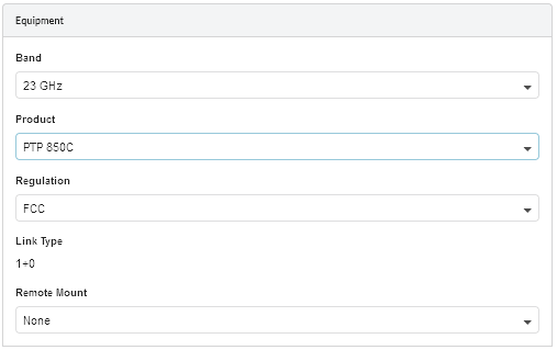
Equipment (licensed bands)
Equipment Parameters
Band: Select the frequency band used by the link.
Product: Select the PTP bridge product with appropriate RFU where available. For further information on the RFU types see the associated product User Guides.
Regulation: Select the regulation that applies to the region in which the link is located.
Encryption Variant: (PTP 820A Only) Select the encryption option for the link.
Link Type: Link Types vary according to the product, not all products support all Link Types
Defaults to 1+0 for a basic single link configuration.
If using Hot Standby equipment click 1+1 Hot Standby, 1+1 HSB Radio Protection, 2x1+0 Unit Redundancy or 1+1 HSB with TCC Redundancy, for more information, see Setting Hot Standby Protection (1+1).
If using Spatial Diversity equipment
For PTP 820G, click 1+1 Hot Standby
For PTP 820C Spatial Diversity click on 2+0 Spatial Diversity or 2+2 Spatial Diversity
For PTP 820A Spatial Diversity click on 1+1 Hot Standby or 2+2 SD XPIC (BBS)
For more information, see Setting Diversity
If using 2+0 Single Antenna click either 2+0 Co-Polar(ACCP), 2+0 Cross Polar (ACAP) or 2+0 XPIC (CCDP), for more information, see Setting 2+0 Single Antenna.
If using Hot Standby and 2+0 click either 2+2 Co-Polar (ACCP), 2+2 Cross-Polar (ACAP) or 2+2 XPIC (CCDP)
If using 4+0 Antenna Sharing click either 4+0 Co-Polar (ACCP), 4+0 Cross-Polar (ACAP) or 4+0 XPIC (CCDP)
Remote Mount: Select which end of the link requires the antenna to be remote mounted.
Ethernet Configuration:
Select the required Ethernet Configuration for 2+0 or 4+0 Link Types. (PTP 820 and PTP 850 Only)
Single Ethernet (MC-ABC) requires the following:
one Ethernet cable per ODU (PTP 820C, PTP 820C HP or PTP 850C) or per IDU (PTP 820G)
one MC-ABC key per Tx
Note that Single Ethernet (MC-ABC) restricts the capacity to a single Ethernet connection. (1 Gbps for GbE, 2.5 Gbps for 2.5 GbE or 10 Gbps for 10 GbE)
Multiple Ethernet (with or without LAG) requires the following:
two Ethernet cables per ODU (PTP 820C or PTP 850C) or IDU (PTP 820G)
no additional keys to implement LAG
Multiple Ethernet (with LAG) requires internal PTP 820 LAG.
Multiple Ethernet (without LAG) requires link aggregation in the connected external switches.
L1 Link Bonding (PTP 850C Only) - for 4+0 configurations using only one data drop cable per end with short interconnect cables between the two radios
RFU MC-ABC (PTP 820A Only) - for RFU based MC-ABC operation. Cabling and MC-ABC activation key is similar to Single Ethernet (MC-ABC)
TCC MC-ABC (PTP 820A Only) - for TCC based MC-ABC operation. Cabling and MC-ABC activation key is similar to Single Ethernet (MC-ABC)
RFU MC-ABC with L1 Link Bonding (PTP 820A Only) - For 4+0 configurations, RFU based MC-ABC requires L1 Link Bonding.
Product Configuration (unlicensed bands)
Select the product parameters. The fields that are displayed in the “Product Configuration” box will change depending on the type of equipment selected. For example, when a PTP 450i is selected the Color Code field is displayed.
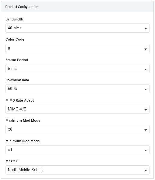
PTP Product Configuration (unlicensed bands)

Some parameters are required when configuring the product but are currently not used in the LINKPlanner calculations, they will be used in future releases. These items are identified as “(information only)” in the descriptions below.
Product Configuration Parameters
Bandwidth: Select the channel bandwidth.
E1/T1: (PTP 670 and PTP 700 only). If the link is to carry telecoms traffic, select the number of E1 or T1 links required. For more information, see Optimizing E1 or T1 Latency.
Optimization: (PTP 670 and PTP 700 only). Select the optimization for the link, either for IP Traffic or TDM Traffic. If TDM is enabled, the link is optimized automatically for TDM traffic/latency.
Sync: (PTP 670 and PTP 700 only). Defaults to Disabled. TDD Synchronization will be added in a future release
Symmetry: (PTP 670 and PTP 700 only). Select the link operation (Adaptive, Symmetric, 2:1, 3:1 or 5:1 - options are dependent on Product and other configuration settings).
Dual Payload: (PTP 670 and PTP 700 only). Allow dual-payload modulation modes for better throughput.
Highest Mod Mode: (PTP 670 and PTP 700 only). Select the highest modulation mode for the Ethernet traffic to limit the maximum throughput rate, default is 256 QAM 0.81 (no limit). Dual or Single will be automatically selected depending on the setting for Dual Payload.
Maximum Mod Mode: (ePMP, PTP Mode or PTP 450 family only). Select the highest modulation mode for the Ethernet traffic to limit the maximum throughput rate, default for ePMP 11n is MCS15 and 11ac is MCS 9 (256QAM 0.83 Dual).
Minimum Mod Mode: (PTP 450 family only) Select the lowest modulation mode for the traffic.
Lowest Ethernet Mode (PTP 670 and PTP 700 only). Select the lowest modulation mode for the Ethernet traffic to achieve the required throughput rate, default is BPSK 0.63 Single.
Lowest Telecoms Mode (PTP 670 and PTP 700 only). When a link is configured for E1 or T1 telecoms traffic, select the lowest modulation mode to achieve the required latency. For more information, see Optimizing E1 or T1 Latency.
Color Code: (PTP 450 and 450i only). Select the Color Code for the link (information only).
Frame Period: (PTP 450 and 450i only). Select the Frame Period.
Downlink Data: (PTP 450 and 450i only). Set the proportion of the link to be used for throughput from the Master to the Slave.
DL/UL Ratio: (ePMP and PTP 550 only). Select the required DL/UL Ratio, where DL is the proportion of the link to be used for throughput from the Master to the Slave.
Master: Select which site is the master.
Gb Ethernet Port: (ePMP 1000 only). Select whether each end of the link requires equipment with a GbE port instead of an FE port (the FE port will limit the maximum throughput if selected at either end of the link). Select Gb Ethernet Port at the Master if the link has to be synchronized.
Product Configuration (licensed bands)
Select the product parameters. The fields that are displayed in the “Product Configuration” box will change depending on the type of equipment selected. For example, when a PTP 850E is selected the ACMB field is displayed.
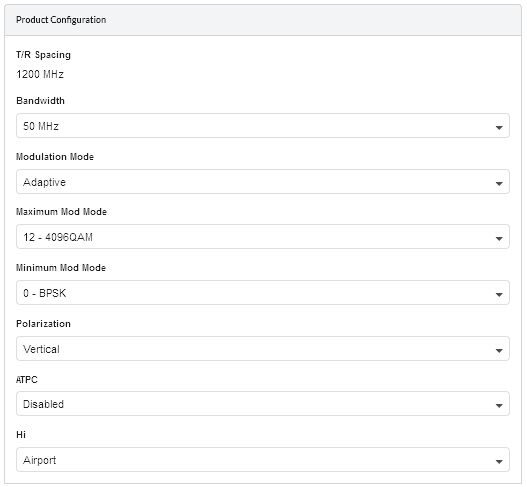
PTP Product Configuration (licensed bands)
Product Configuration Parameters
T/R Spacing: Select the difference between transmit and receive frequencies (MHz).
Bandwidth: Select the channel bandwidth.
Modulation Mode: Select the modulation mode to be used by the equipment. If Adaptive is selected then additional fields are displayed.
ACMB: Select whether the link will be configured with Adaptive Coding Modulation and Bandwidth enabled or disabled. When enabled additional modulation modes become available which reduce the bandwidth by one half or one quarter.
Maximum Mod Mode: Select the maximum modulation mode that the equipment will use in adaptive mode. Only displayed when Adaptive modulation is selected.
Minimum Mod Mode: Select the minimum modulation mode that the equipment will use in adaptive mode. Only displayed when Adaptive modulation is selected.
Polarization: Select the antenna polarization to be used (Horizontal or Vertical). For 2+0 Co Polar, the same polarization is used on both links, for 2+0 Cross Polar and 2+0 XPIC Link Types both polarizations will be used, select the polarization for one of the links and the other will update automatically.
ATPC: Select whether the link will be configured with ATPC enabled or disabled. In some bands and regulations it is compulsory to use ATPC, in which case it will not be possible to disable the function.
Hi: Select which site is the nominated Hi end for the link. This site will only have access to the higher end of the frequency range and the other end of the link will only have access to the lower frequencies in the band.
Header Compression: Select the level of header compression required.

TDM Equipment Configuration (PTP 820G Only)
TDM Configuration (PTP 820A and PTP 820G Only)
Select the E1/T1 required for this link
TDM Type: Defaults to None, if TDM is required select either E1 or T1.
E1s (or T1s): Select the number of E1 or T1 circuits to be carried across the wireless link. In 2+0 configurations the maximum of 16 is shared between the two paths.