Configuration at Each End
Use this section to evaluate different antenna configurations at each end of the link. Enter data about the antenna, transmission power and interference density (at both ends). When parameters are changed the ![]() icon is enabled and parameters affected are shown in blue. Select
icon is enabled and parameters affected are shown in blue. Select ![]() and any dependent parameters and the Performance Summary section is updated automatically to show the effect upon the Mean Throughput, Minimum Throughput and Availability. The two ends are each divided into three parts:
and any dependent parameters and the Performance Summary section is updated automatically to show the effect upon the Mean Throughput, Minimum Throughput and Availability. The two ends are each divided into three parts:
Data that affects both transmission and reception: Antenna, Antenna Height and Cable Loss. These parameters are common for 2+0 links
Data that affects transmission only: Maximum EIRP, Maximum Power. These parameters are set independently for 2+0 links
Data that affects reception only: Interference Density. These parameters are set independently for 2+0 links
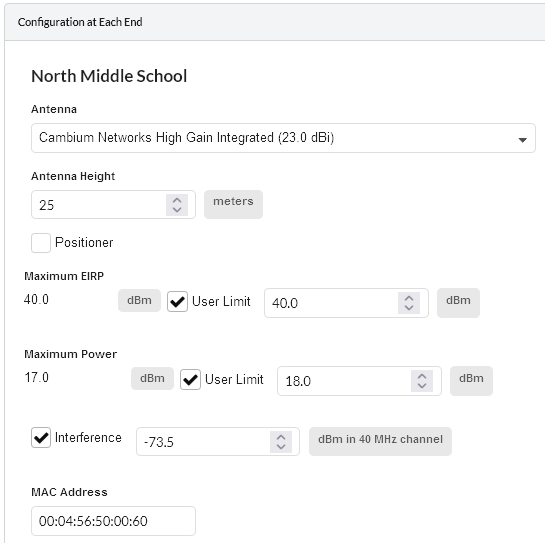
Configuration at Each End (one end shown)
Antenna: Select the required antenna from the drop-down list. If operating in the unlicensed band and the required antenna is not in the list, click Other… and enter the details in the User Defined Antenna page. Antennas may also be viewed, created, edited and deleted from the Antennas page. Licensed band antennas may only be viewed, at present only Cambium supplied antennas are supported at these frequencies.
Antenna Height (meters): This is the height of the antenna AGL, not the height above the building on which it is mounted. The Profile visualization is automatically updated in response to changes in Antenna Height.
Positioner: (PTP 450i and PTP 670 Only) Tick this box to add the positioner equipment to the BOM. Select for each end of the link which requires a positioner. This is only available for integrated antennas.
Spatial Diversity: (PTP 670 Only) Tick this box to enable spatial diversity. Not available for Integrated antennas.
Diversity Spacing: (PTP 670 Only) Set the Diversity Spacing required between the two antennas
Reflection Mitigation: (PTP 670 Only) Tick this box to enable the diversity spacing to be used for Reflection Mitigation. Note that this will reduce the performance prediction to only use the single payload modulation modes, as dual payload cannot be guaranteed during periods of reflections
Cable Loss (dB): This field is not displayed for INTEGRATED antennas. If a non-integrated antenna is used, power may be lost in the cable connection between the radio and the antenna, therefore the Cable Loss must be estimated. To set Cable Loss enter the estimated loss in the dB field.
Maximum EIRP (dBm): The maximum available Equivalent Isotropic Radiated Power. The default value is determined by the Band, License, Product and Antenna. If a lower user-defined limit is required, tick the User Limit box and enter the value. In response, the default Maximum EIRP is automatically reset to the User Limit.
Maximum Power (dBm): The maximum available transmission power. The default value is determined by the Band, License, Product and Antenna. If a lower user-defined limit is required, tick the User Limit box and enter the value. In response, the default Maximum Power is automatically reset to the User Limit.
Tx Frequency: (PTP 550, 60 GHz cnWave and PTP 450v Only) To change transmit frequency for the link, select the channel from the drop down list. The same channel is used for both transmit and receive.
Tx Golay: (60 GHz cnWave Only) Set the Golay code. This parameter is the same for both ends of the link.
Polarity: (60 GHz cnWave Only) Set the Polarity of the link. If set to Auto both ends of the link will be Auto. For Odd and Even each end of the link will be opposite.
Interference (dBm): This is the amount of site noise in the selected channel bandwidth, expected at the antenna connector. This noise is assumed to be a constant power added to the thermal noise of the front end of the wireless. The bandwidth displayed depends on the bandwidth selected in the Equipment Settings box (in this example it is 40 MHz). To enter Interference, tick the box and update the default value. If the link has been set up and mean power measurements from DFS are available, then use these measurements.
MAC Address: This is an optional field where the MAC Address can be recorded.
Licensed bands
For links operating in licensed bands, the following additional attributes are displayed:
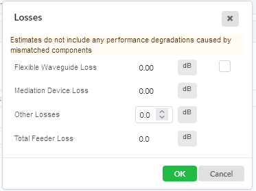
Feeder Loss: This replaces the Cable Loss field in the unlicensed band. The licensed band equipment uses a flexible waveguide, which is of a fixed length and the feeder loss is automatically entered when a non-integrated antenna is used.
To change the automatic feeder loss click Edit and enter any additional loss in the Other Losses field. The Flexible Waveguide Loss can be deselected, which will remove it from the loss calculation and will also remove the associated Flex Waveguide equipment item from the BOM. Once any changes are made to the Losses panel, Feeder Loss will change to Maximum Feeder Loss and will show the maximum loss for either transmit or receive. The loss on transmit is incorporated into the Maximum EIRP value.
Additional Feeder Losses in Licensed Band
Power: (PTP 850 Only and PTP 820A Only) Choose whether to use PoE or DC power
Ethernet Cable: (PTP 850 Only) Choose the data drop cable type from Cat 6A and Fiber options.
IDU-RFU: (PTP 820A Only) Read only. Shows the TCC or RIC-D card RFU interface used and the drop cable type between the radio and the modem unit from Cat 6A and Fiber options.
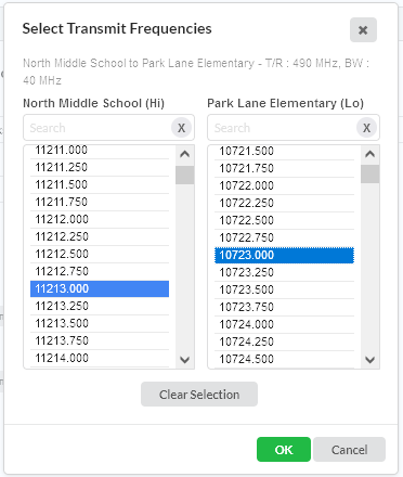
Tx Frequency: To change transmit frequencies at either end of the link, click on Select…. The Select Transmit Frequencies dialog is displayed. The end of the link which has been selected as Hi will show the higher frequencies in the band.
Select Transmit Frequencies
For 2+0 Co Polar and 2+0 Cross Polar Link Types, the Tx Frequency pairs for each path is displayed. Select the frequency pair for one path and the available frequencies for the other path are filtered to show only valid Tx frequency pairs, select the second frequency pair from the modified list.
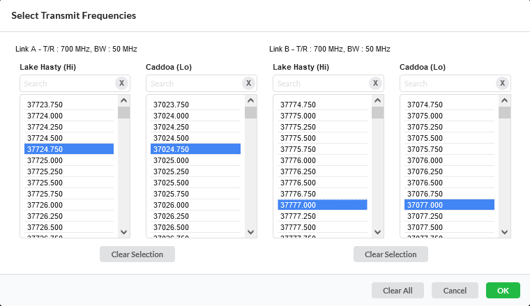
Select Transmit Frequencies 2+0 configuration
Click Clear Selection to remove selected frequencies from the list.

The BOM will not include any ODU part numbers - before ordering make sure that the correct ODU part numbers are included by choosing the appropriate frequencies.