Subscriber Module Description and Equipment
General
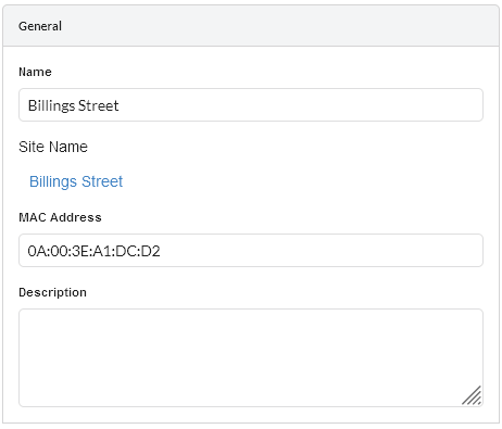
Enter the Name and Description of this link. The MAC Address of the equipment may also be added.
Subscriber Module General
Equipment
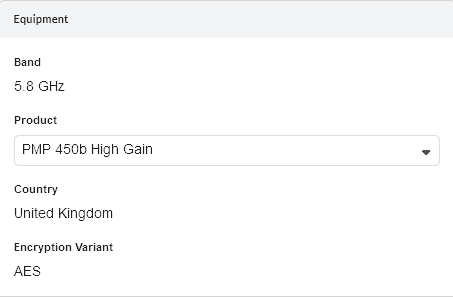
Select the available subscriber parameters for this link.
Subscriber Module Equipment
Equipment Parameters
Number of Component Carriers (PMP 450v Only): Select the number of Component Carrier for the Subscriber Module
Component Carrier (PMP 450v Only): Select the Component Carrier for the Subscriber Module
Band: Read only value reflecting the band selected at the Network Device.
Product: Select from the available list, based on the product selected for the Network Device.
Country: Read only value reflecting the country selected at the Network Device.
I/O Connectivity (N500 Only): Select Expanded to get the additional IO port, used for product selection only.
Sync Input (N500 Only): Read only value reflecting the synchronization option for the link.
Product Configuration
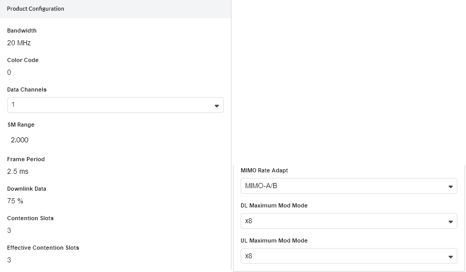
Select the product parameters. The fields that are displayed in the “Product Configuration” box will change depending on the type of equipment selected. For example, when a PMP 450i is selected, the Color Code field is displayed.
Subscriber Module Product Configuration
Product Configuration Parameters
Band Setting (N500 Only): Read only value reflecting the band setting value from the ND (ISM or Licensed).
T/R Spacing (N500 Licensed Only): Read only value reflecting the difference between transmit and receive frequencies (MHz).
Bandwidth: Read only value reflecting the bandwidth selected at the Network Device. Available under Component Carriers section when the ND is PMP 450v 4x4.
Modulation Type (N500 ISM Only): Read only value reflecting the group of modulation modes to use.
Channel (60 GHz cnWave Only): Read only value reflecting the channel selected at the Distribution Node.
Color Code (PMP 450 and 450i): Read only value reflecting the color code selected at the Network Device.
Link Golay (60 GHz cnWave Only): The Golay code for just this link between the DN and CN, default to the same as the DN, so that all links on the DN start the same.
Polarity (60 GHz cnWave Only): Read only value reflecting the Polarity selected at the Distribution Node
Capacity (PMP 450 only): Select the capacity limit for the Subscriber Module.
Data Channels (PMP 450 and 450i only): Defaults to 1. Select the number of Data Channels required for the Subscriber Module, range is 1 to 4.
SM Range: Read only value reflecting the SM range selected at the Network Device.
SM Modulation Mode: (N500 Only). Read only value reflecting the modulation mode to be used by the SM equipment.
SM Maximum Mod Mode: (N500 Only). Read only value reflecting the maximum modulation mode that the SM equipment will use in adaptive mode. Only displayed when Adaptive modulation is selected.
SM Minimum Mod Mode: (N500 Only). Read only value reflecting the minimum modulation mode that the SM equipment will use in adaptive mode. Only displayed when Adaptive modulation is selected.
Hop Pattern: (N500 only). Read only value reflecting the uniform step interval for DTS modulations. A value of 0 sets the frequency to a single channel, a value of 1 creates a pseudo random hopping sequence. A value of 1 must be used when Modulation Type = FHSS.
MMS Hop Offset: (N500 only). Read only value reflecting the MMS Hop Offset for the link.
SM Max Payload Bytes: (N500 only) Read only value reflecting the maximum packet size at the SM. Maximum value is 1600 Bytes. Minimum value for fixed modulation mode is 64 Bytes, in adaptive mode, the minimum may be higher than this dependent on the configured Max and Min Modulation modes. Reducing the packet size will reduce the data rate from the quoted data rate per mode.
Polarization: (N500 Only). Read only value reflecting the ND antenna polarization (Horizontal or Vertical).
Frame Period: Read only value reflecting the frame period selected at the Network Device.
Downlink Data (PMP 450 and 450i only): Read only value reflecting the downlink data ratio selected at the Network Device.
DL/UL Ratio (ePMP only): Read only value reflecting the downlink data ratio selected at the Network Device.
Maximum Mod Mode (ePMP Only): Set the maximum modulation for the Subscriber Module on the uplink to the Network Device.
Max Registrations Allowed (ePMP, PMP 450 and 450i Only): Read only value reflecting the maximum number of Subscribers selected at the Network Device.
Contention Slots (PMP 450 and 450i Only): Read only value reflecting the number of contention slots selected at the Network Device.
DL Maximum Mod Mode (PMP 450 and 450i Only): Set the maximum modulation mode for the Subscriber Module on the downlink from the Network Device to the Subscriber Module.
UL Maximum Mod Mode (PMP 450 and 450i Only): Set the maximum modulation mode for the Subscriber Module on the uplink from the Subscriber Module to the Network Device.
Antenna Configuration
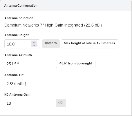
Select the antenna and its height. The orientation is calculated automatically.
Network Device Antenna Configuration
Antenna Configuration Parameters
Antenna Selection: Select the antenna for the Subscriber Module. If the Subscriber Module supports connectorized antennas and the required antenna is not in the list, click Other… and enter the details in the User Defined Antenna page. Antennas may also be viewed, created, edited and deleted from the Antennas page.
Antenna Height: Select the height of the Subscriber Module above ground level
Positioner: (PMP 450i Only) Tick this box to add the positioner equipment to the BOM. This is only available for integrated antennas.
Calculate Loss: (N500 Only). Tick the Calculate box to select the type of cable that connects the radio to the antenna. The Cable Loss field is automatically updated.
Cable Length: (N500 Only). The length of cable required to connect the radio to the antenna. The Cable Loss field is automatically updated.
Cable Loss: Only displayed for external antennas, read only value for PMP 450 antenna options.
Antenna Azimuth: Calculated angle from Subscriber Module to Network Device
Antenna Tilt: Calculated elevation angle from Subscriber Module to Network Device - a negative value indicates downtilt is required.
ND Antenna Gain: Calculated value of the Network Device sector antenna in the direction of the Subscriber Module.
Sector (60 GHz cnWave Only): Select sector of the DN. Only available if close to boundary between the sectors otherwise read only.
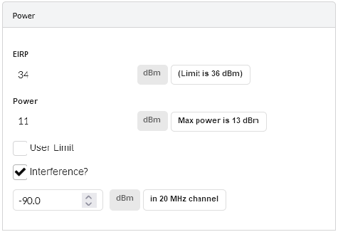
Power
Set the power and interference parameters.
Subscriber Module Power
Power Parameters
EIRP: Read only value showing the EIRP of the antenna, if the country selected has a regulatory limit this value is shown in brackets underneath.
Power: Calculated value to meet the SM Receive Target Level at the Network Device, if the country selected has a regulatory limit (or an implied limit to meet the EIRP limit) the value is shown as “Max Power” in brackets underneath.
User Limit: Tick the User Limit box and enter a value to limit the maximum transmit power used by the Subscriber Module. This value can only be used to lower the value from the default calculated.
Interference: This is the amount of site noise in the selected channel bandwidth, expected at the antenna connector. This noise is assumed to be a constant power added to the thermal noise of the front end of the radio. The bandwidth displayed depends on the bandwidth selected in the Product Configuration Settings box (in this example it is 20 MHz). To enter Interference, tick the box and update the default value. If the Network Device has been set up and mean power measurements are available, then use these measurements.
Component Carrier
This section is available only when the Network Device is PMP 450v. This section displays read-only parameters for the selected component carrier.
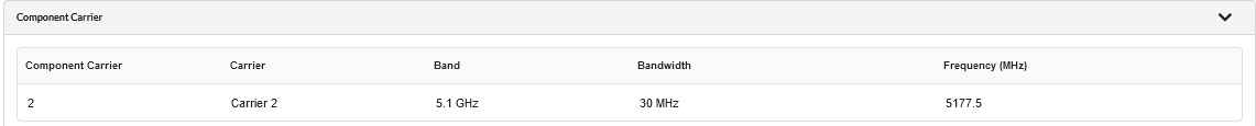
Component Carrier