Viewsheds
Viewsheds indicate all the locations in the area surrounding a chosen place that are considered to be Line-of-Sight for a given tower height and subscriber height.
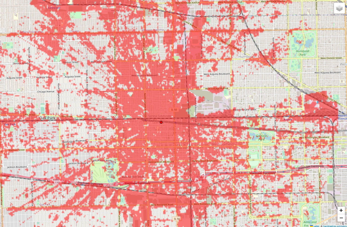
A viewshed on the map
Creating a viewshed
Click
 on the right hand side menu.
The Viewshed Mode window opens (Viewshed Map Menu), click
 . See Viewshed Calculation for details on Optical and Radio LOS.
The Viewshed Configuration Dialog is displayed
Configure the options in the Viewshed Configuration Dialog.
See Viewshed Configuration for information about the options in this dialog.
Click
 to start the calculation.
After starting the calculation, a progress notification will be displayed. Multiple calculated viewsheds may be displayed on the map at the same time.
Viewshed Progress Notification
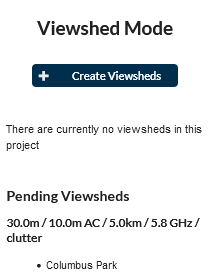
Once the calculation has finished, the menu in the Viewshed Map Menu will be populated with an entry for each viewshed created. This menu contains a list of viewsheds that have been previously calculated. Use the radio button ![]() to display the desired viewshed image or select
to display the desired viewshed image or select ![]() to show no image.
to show no image.
For each viewshed entry in the list, the following information is shown:
Tower Height
Subscriber Height
Depending on the configuration of the subscriber height, either one or two heights will be shown. One height will be shown for “Use height above ground” and “Use height above clutter” and two will be shown for “Use min height above clutter”.
The subscriber heights are followed by an acronym indicating how the subscriber height is used by LINKPlanner.
AC - Above Clutter: This height value will always be added on top of the height of the clutter at any given point.
AGL - Above Ground Level: This height value will always be added on top of the ground at any given point, regardless of whether clutter is present.
Viewshed Radius
Frequency (for Radio LOS Viewsheds only.)
Clutter (indicates whether clutter was included in the calculation)
The color of the Viewshed
Click the ![]() next to the viewshed configuration in the list to create a new viewshed using same configuration.
next to the viewshed configuration in the list to create a new viewshed using same configuration.
Click the ![]() next to a viewshed in the list to delete it.
next to a viewshed in the list to delete it.
Viewshed Map Menu
Click the ![]() button to hide viewsheds for all sites which are currently displaying any.
Click the
button to hide viewsheds for all sites which are currently displaying any.
Click the ![]() button to show viewsheds for all sites if there are no viewsheds being shown.
button to show viewsheds for all sites if there are no viewsheds being shown.
Viewshed Configuration
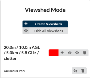
Viewshed Configuration Dialog
The first section of the viewshed dialog is concerned with the network sites to be chosen (select from the list) or you can select locations on the map, by clicking on Select locations in map and then clicking on the map, which will add new network sites to the map.
The second section of the viewshed dialog is concerned with the general characteristics of the viewshed. In the Tower Height section choose between Use site Maximum Height? which takes the site height configured in the network sites list and Use Tower Height? which uses a fixed height above ground. For High Resolution Viewsheds there is an additional option for Use Tower Height Above Clutter? which takes a fixed height above the surface (ground + clutter)
Name |
Description |
|---|---|
Create High Resolution Viewshed |
Tick this box to create a High Resolution Viewshed for 60 GHz. This requires Lidar data to be available for the area. |
Site Max. Height |
The maximum height of the network site above ground. This does not include clutter. |
Tower Height above Ground |
The height of the tower above ground. This does not include clutter. |
Tower Height above Clutter |
The height of the tower above clutter. This does include ground+clutter. |
Radius |
The maximum distance of a Subscriber away from the ND that the calculation will consider. |
Radio LOS |
Tick this option to include Frequency Band in the calculation. |
Band |
The frequency to use. This is only available for Radio LOS Viewsheds. |
Color |
The display color of the viewshed. The color is only used to differentiate between multiple viewsheds. |
Use Clutter? |
Tick this to include clutter heights in the calculation. The heights will be taken from the project file. |
The third section is concerned with how the heights of the subscribers are used.
Name |
Description |
|---|---|
Use height above ground? |
Consider the height of the Subscriber to always be the height above ground level, using the Height Above Ground value above. |
Use height above clutter? |
Consider the height of the Subscriber to always be the height above clutter, using the Height Above Clutter value above. |
Use min height above clutter? |
Consider the height of the Subscriber to be the minimal value which exceeds the clutter height at any given point using both of the Subscriber height values above. This is calculated as the maximum value of the Height Above Ground or the clutter height at that point added to the Height Above Clutter. |
Height Above Ground |
The height of the Subscriber above ground level. |
Height Above Clutter |
The height of the Subscriber above ground level plus clutter height. |
Viewshed Calculation
Optical LOS Viewsheds are calculated by only considering the antenna and tower heights at each end and the ground heights and clutter heights (if included) throughout the entire profile. The tower height (ND) is always the height above ground and the SM height is above ground when clutter is not included and above clutter when it is included. These are typically faster to calculate but will result in more optimistic coverage.
Radio LOS Viewsheds will consider the same information as Optical, but determine Line-of-Sight based on a calculated Fresnel zone for each location. Any intersection between terrain, clutter and the Fresnel zone is considered to be Non Line-of-Sight so viewsheds will be pessimistic in Near Line-of-Sight cases and may differ from LINKPlanner profile results.
Viewshed Information
Due to performance reasons, the viewshed calculation will sample the terrain at slightly different locations to the individual LINKPlanner path profiles which may lead to differences between the two results, for example some areas may be shown as non line-of-sight in the viewshed region but could still yield a viable link or vice versa.
The underlying terrain and clutter data used to calculate the viewsheds is the same as the individual path profiles, see Path Profiles. The data is sampled at approximately 30 meter intervals but may be sampled in slightly different locations to the individual path profiles. Where the data resolution exceeds 30 meters, it is resampled to 30 meters but is not any more accurate (this is notably the case for clutter data in Europe and non-US areas). Missing data values are considered to be 0 meters.
At certain zoom levels on the map, parts of the viewshed may appear out of focus - this is due to limitations with the browser scaling the viewshed images, but locations roughly within the 30 meter block of the colored area will be Line-of-Sight.